Build Smart Home System with Node-RED
Use the Mixtile Edge 2 Kit as your Smart Home project’s control and monitoring center, efficiently managing data from temperature, humidity, brightness, UV sensors, etc.
Use the Mixtile Edge 2 Kit as your Smart Home project’s control and monitoring center, efficiently managing data from temperature, humidity, brightness, UV sensors, etc.
The Mixtile Edge 2 Kit used as Smart Home center integrates Zigbee technology and machine learning algorithms to automate the home and improve user comfort. The Mixtile Edge 2 acts as a central coordinator of the Zigbee and BLE network, managing data from temperature, humidity, brightness and UV sensors. This data is used not only to intelligently control devices in the home, such as lights and thermostats, but also to provide personalized clothing recommendations based on the weather conditions outside. The system uses a logistic regression model, integrated through Node-RED, to analyze sensor data and generate accurate suggestions, facilitating quick and efficient decisions for the user.

About Mixtile Edge 2 kit:
Mixtile Edge 2 Kit is a high-performance IoT gateway designed specifically for industry applications. More details about this device here.
Most important specifications:
– processor Rockchip RK3568, an quad-core processor (4xCortex A55);
– support NPU (Neural Processing Unit);
– maximum RAM memory support is 2/4GB RAM LPDDR4x, enough for video or AI applications;
– support for eMMC (16/32 GB);
– connectivity: USB 3.0, HDMI 2.1, Gigabite Ethernet, WiFi 6. Bluetooth 5.2;
– compatible with Linux (Debian, Ubuntu); also Home Assistant and Android can be installed on this PC.
Usage: Mixtile Edge 2 Kit will be the “heart” of smart home and will act as an control center. Some of the sensors and external devices will use the Zigbee protocol to communicate with Mixtile Edge 2 Kit and other (sensors from weather station) will comunicate via MQTT over WiFi, in local network. External devices connected to Smart home command center will use ESP32-C6 dev boards, because these have Zigbee protocol built-in, CC2530 based dev boards and other devices will be purchased from the market (to test the compatibility with this system).
To achieve this, I will setup this device using the steps below.
The Mixtile Edge 2 Kit was come with Debian 11 installed. I have to install and configure Node-Red in order to communicate with some sensors located in my home, using MQTT protocol over WiFi.
A. Install the NodeRed on Mixtile Edge 2 Kit: I used the instructions from this link.
First make sure that Debian package list repository is up to date. to do that, use the following lines:
sudo apt update

sudo apt upgrade -y
Then, install nodejs for Debian (latest version for nodejs is 20, according to this link):
curl -fsSL https://deb.nodesource.com/setup_20.x | sudo bash -Then, install npm
sudo apt-get install nodejs -yTo verify if the nodejs and npn is installed, use the following commands to verify:
node -v
npm -v
The result from my Mixtile Edge 2 Kit:

nodejs and npm versions
Now we have install Node-Red using the following command:
udo npm install -g --unsafe-perm node-redNote: after the Node-Red installation, it is possible to see in console an npm notice to update the latest version, using npm install -g npm@version, where version could be 10.8.3
Start Node-Red:
node-red
Node-red started:

1/2 · Node-red in browser

2/2 · Node-red in console
Note: install Node-Red Dashboard module, to create UI instruments and buttons/sliders to interact with IoT devices:
http://localhost:1880/ui --> if Node-Red UI is accessed from Mixtile2 Edge kit
OR
http://mixtile_IP:1880/ui --> if Node-Red is accessed from the same network
To find the Mixtile Edge 2 Kit IP, type this in console:
hostname -I
Mixtile Edge 2 Kit IP
B. Install Mosquitto MQTT broker (link with instructions):
sudo apt install -y mosquitto mosquitto-clientsTo make Mosquitto auto-start when Mixtile Edge 2 Kit start, run the following command:
sudo systemctl enable mosquitto.serviceTest the installation by running:
sudo systemctl status mosquittoNow, configure Mosquitto broker to accept remote access to communicate with other IoT devices:
– Run the following command to open the mosquitto.conf file:
sudo nano /etc/mosquitto/mosquitto.conf– go to on the top on the file and add this line:
per_listener_settings true– go to at the end of the file and add these lines:
listener 1883
allow_anonymous truesudo systemctl restart mosquitto– to verify if Mosquitto is running, run the following command:
sudo systemctl status mosquitto
Mosquitto config file modified
Start Node-red using:
node-redFinal: Node-Red working, Mosquitto broker working and display data on Node-Red UI:

Node-red working and display data
Note: the data sent to Node-Red on Mixtile Edge 2 Kit come from my project https://www.hackster.io/popa-mihai/beaconhome-92ec7d ; this project is used only to test the configuration of whole chain, from distant device (in my case ESP32 reading some BLE beacon sensors) to Node-Red UI. Meanwhile, this project was moved from RPI Zero to Mixtile Edge 2. The change means only replacing the IP address of the RPI Zero with that of the Kixtile Edge 2 Kit in the ESP32 code; see the project lins and code.
One of the interesting option of Mixtile Edge 2 Kit is the posibility to comunicate with other devices using Zigbee and Z-Wave protocol.
In this project I will use only Zibgee protocol, due to the fact that Zigbee do not need any license, the devices are relatively cheap and can be even created using ESP32-C6 or CC2530 or similar dev boards.
Board used for Zigbee and Z-Wave communication is this one: Mixtile 2-in-1 Zigbee & Z-Wave mPCIe Interface Module. More data about this board here.
This board has an mPCIe interface but communicates with Mixtile Edge 2 Kit through 2 USB ports, creating two serial connections.
To see this USB connection, type this command in console:
ls /dev/ttyACM*The result should be:
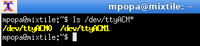
Mixtile 2-in-1 Zigbee and Z-Wave USB connections
Note: ttyACM0 is Z-Wave and ttyACM1 is Zigbee
To establish communication link between Zigbee board and Node-Red, I will use Zigbee2Mqtt bridge. Details for what is and how to configure here.
Now, proceed to install Zigbee2MQTT:
sudo git clone https://github.com/Koenkk/zigbee2mqtt.git /opt/zigbee2mqtt
cd /userdata/zigbee2mqtt/
sudo npm install
Configure Zigbee2Mqtt to use the Zigbee board. To do that, modify the file:
sudo nano /userdata/zigbee2mqtt/data configuration.yamlIn this file, modify the serial port to /dev/ttyACM1 and add adapter type ezsp:

Zigbee2mgtt config file modified
Obs: because the Mosquitto MQTT server and Zigbee2Mqtt run on the same machine, then we will not create, for the moment, user and pass in configuration.yaml file (because Mosquitto accept anonymous connections).
Next, add used to specific groups (after that, restart Mixtile Edge 2 Kit):
sudo usermod -a -G uucp $USER
sudo usermod -a -G tty $USER
sudo usermod -a -G dialout $USER
Start Zigbee2Mqtt:
cd /userdata/zigbee2mqtt/
npm start
The result should look like this:

Zigbee2mgtt started
Now, we continue with connection between Zigbee2Mqtt and Node-Red.
Before configure Node-red to send or receive commands/data to end-devices using Zigbee2Mqtt, We have to activate Zigbee2Mqtt UI. For that, We have to add the following lines to configuration.yaml file:
frontend:
  port: 8080
The modification should look lite this:

Zigbee2mgtt UI activation
The modification should look lite this:

Zigbee2mgtt UI in browser
In this stage, the whole chain is set and ready to to be configured with sensors, buttons, out-devices and so on.
For this step, I will use some sensors from the market (for example: Tuya temperature sensor, Sonoff button) and other sensors and devices based on development boards, as ESP32-C6 Zigbee enabled or TI CC2530.
A. First, will proceed to configure End Devices based on ESP32-C6 that will be connected to our Zigbee network; these devices will be flashed with examples provided by ESP32 Arduino library, as following:
To do this, we have to install Arduino IDE on Mixtile Edge 2 kit (using sudo apt install arduino in Linux CLI) and then will configure for using ESP32 with info from here.
Now, We are ready to flash both ESP32 boards. First, we will flash the temp sensor example. Then, We continue with second board, used as Light Bulb.
Obs: be sure that the settings for boards are following these options:
Tools -> Board.Tools -> Zigbee mode: Zigbee ED (end device)Tools -> Partition Scheme: Zigbee 4MB with spiffsTools -> Port: xxx where the xxx is the detected COM port.Details about this here.

1/3 · Temperature sensor example

2/3 · Light Bulb example

3/3 · Flash settings
In this moment we are ready to add these two end devices in Zigbee2Mqtt using Mixtile Edge 2 kit as coordinator.
Start Zigbee2Mqtt (or check if is started already):
cd /userdata/zigbee2mqtt/
npm start
Power up the ESP32-C6 used as temperature sensor and ESp32-C6 used as Light Bulb; go to in browser and open Zigbee2mqtt UI. Here We will find (after few seconds), two devices:

Both ESP32-C6 devices recognized and added in Zigbee2Mqtt
OBS: the IEEE address is unique for each ESP32-C6 chip and act like an MAC address. In Zigbee2mqtt UI is a tab named Friendly name; from here We will give a more friendly name for devices added instead using the MAC address. We can see also the network components and other device properties.

ESP32 Arduino devices named
IMPORTANT: There is something that We have to add in database.db file from /userdata.zigbee2mqtt/data in order to make the example Light_Bulb to work. By default, the Zigbee2mqtt can not read the Zigbee Model and Zigbee manufacturer from theESp32 that act as light Bulb (I assume that the SW installed on ESP32 not sent these info) and We have to add them manually. For that, open the file database.db with
cd /userdata/zigbee2mqtt/data/
sudo nano database.db
and modify the “manufName” and “modelId” the same as for the first End Device, like here:

Light bulb modification in database
This is only available for the example from Arduino IDE used for this test!!!
OBS: after the modification was done in Zigbee2mqtt database, it is necessary to stop and start the Zigbee2mqtt application; for that, use the following commands in cli:
sudo systemctl stop zigbee2mqtt --> used to stop application
sudo systemctl start zigbee2mqtt --> used to start application
Additional, this can be used to restart the zigbee2mqtt application:
sudo systemctl restart zigbee2mqttTo verify if Zigbee2mqtt is running, type this in cli:
sudo systemctl status zigbee2mqttIn case that Zigbee2mqtt was set to start automatically with the PC and the stop and start commands was used to update the database, then use this to be sure that application will start after these modifications
sudo systemctl enable zigbee2mqttOBS: I see that the ESP32C6 used with Arduino example for lamp (Zigbee_Light_Bulb.ino) is not very stable in time and, after few hours is not responding to commands; to get back in the network, sometimes I need to reset it but for most of the times I need to delete it from Zigbee network and pair again. I see that the developers of Arduino Zigbee examples used in Arduino IDE will update soon the libraries and examples for ESP32 and, until then, I will use it as it is.
Important: files used to flash an ESP32 with Zigbee bulb and temperature sensor, from Arduino IDE are attached. From what I see, these examples was removed from ESP32 example (from Arduino for ESP32 examples) and will be updated with a new implementation, with new examples; see here the link to github.
B. Connect commercial sensors, Tuya temperature sensors and Sonoff button, to Zigbee2mqtt (follow the instruction from sensor manual); after few seconds after the sensor is powered up, he new entry is displayed in Zigbee2mqtt Devices window:

Tuya sensor in Zigbee2mgtt Sevices window
OBS: before any operation to add new devices in the Zigbee network, the network should be “opened” to add devices; to do that, press on “Permit join” button from Zigbee2mqtt main screen; this operation is also available anytime when will add a new device in the networl:

Activate add in network for Zigbee devices
Note: this option, “Permit join” is enabled for a limited period of time (aprox 4.2 minutes):

Timer for “Permit all” option
These two commercial sensors, Tuya and Sonoff, displayed inZigbee2Mqtt Dashboard:

1/2 · Commercial sensors displayed in Dashboard

2/2 · Market sensors
C. Connect end-devices based on CC2530. To do that, I followed indication from this site and I configured three CC2530 Zigbee dev boards as a following: one switch, one lamp and one DHT11 sensor.
To flash the CC2530 Zigbee modules hex files, CC Debuger hardware programmer should be used with specific software from Texas Instruments; see here all details. Files used for configuration and hex files for each module will be find in attachment section.
Connections for CC2530 devices:
OBS: all devices created with CC25320 dev board and this application will be reported in Zigbee2mqtt as connected to power supply instead battery and can not use the low power management; this can be used but only in payd verssion; see details in the application site.
More devices will be added to the Zigbee network during the project.

CC2530 devices
For the moment, my Zigbee network contain 8 devices: 2 buttons, 2 temperature sensors and two lamps. Sonoff button control only ESP32-lamp and CC2530 button control both ESP32-lamp and CC2530_lamp. Of course, this configuration can be easy changed from Node-Red.
The final Zigbee network look like this:

1/3 · Zigbee devices

2/3 · Zigbee map

3/3 · Zigbee logs
Information from end-devices are received by the Zigbee2mqtt as following, using topics; below is a log from Zigbee2mqtt where We eill find the broker, topic and parameters::
Info
2024-09-20 20:40:27
z2m:mqtt: MQTT publish: topic 'zigbee2mqtt/Tuya-temp-sensor', payload '{"battery":100,"humidity":26,"humidity_calibration":0,"linkquality":212,"temperature":31.6,"temperature_calibration":0,"temperature_unit":"celsius"}'
In this case mqtt topic is “zigbee2mqtt/Tuya-temp-sensor“; so, this topic should be used in Node-Red to read the data from this end-device:

Confic tpoic from Zigbee2mgtt in Node-Red
Note: Mqtt In broker should contain Server settings as localhost:1883, only in case that both Zigbee2mqtt and Node-Red runs on the same machine (this is my case!).
At the end, the Node-Red config and UI should look like this:
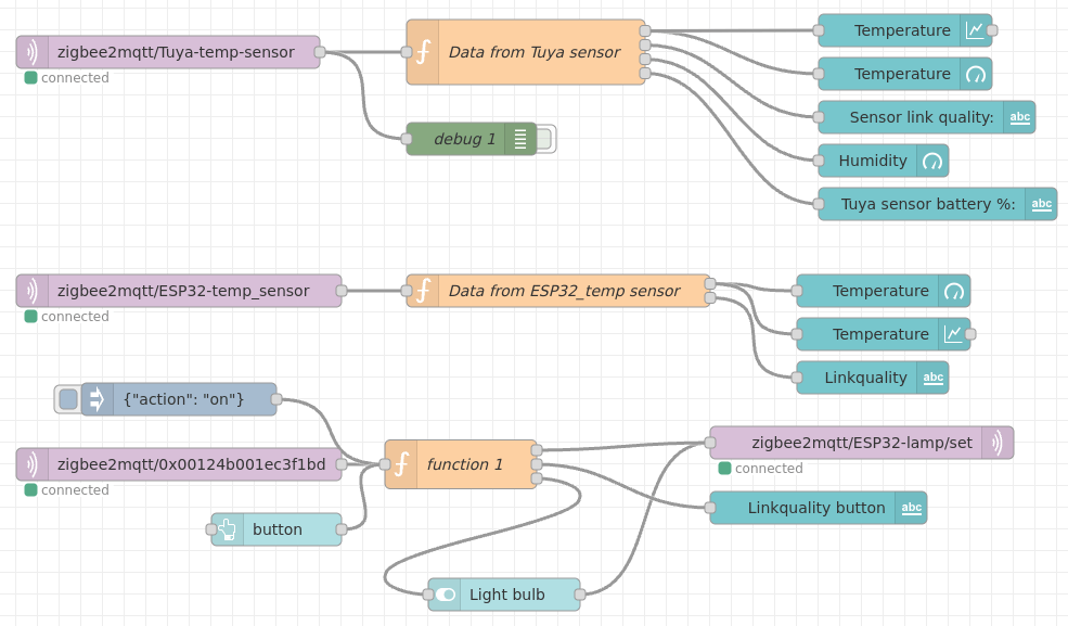
1/2 · Node-Red config

2/2 · Node-Red UI
This is the second part of the Smart Home hub: creating a weather station and predicting what clothes and accessories should be worn outside the home, based on the sensor reading.
In order to predict the recommendation for what should I use when I will go outside, I will use a simple machine learning algorithm, called logistic regression model.
The weather station used in this project is based on 2 ESP32-C6 devices connected together through BLE and another ESP32 used to send data to Mixtile Edge 2 Kit. All the data from the sensors will be stored on sql database and ther the ML model will use these data for prediction.
A. Create weather station. To do that, We use the following components to send the sensor data to sql database:
OBS: I used this solution because there was not enough space on Beetle ESP32-C6 or FireBeetle ESP32-C6 for BLE libraries and MQTT libraries. The third ESP32 receive data through Serial2, connect to local WiFi network, create the MQTT packets and send them to Mixtile, all these based on AT commands.
Files used for BLE server and client are available in download section.
Note: for upload the code for BLE server and client use the instruction from manufacturer page (DFRobot).
Schematic of weather station:

Weather station schematic
Working: the external unit will wait until the client (indoor unit) connects and then will start to send the environmental data with a periodicity at 30 seconds. The indoor unit read data, make some calculation and then will update the TFT only if the data from the last reading is changed; this is done to reduce flickering cause of rapidly updating of TFT; moreover, the data used to update the TFT will be sent over WiFi in MQTT format to Mixtile Edge 2 kit. This is done using another ESP32 with AT commands.
B. Create a database for sensor data. For that, I will use SQLite database. To install SQLite, type this in console:
sudo apt update
sudo apt install sqlite3
To verify if SQLite is installed, type this in console:
sqlite --versionThe answer should be like this:
Weather station schematic
Next, create a database used to store the data from weather sensors. In Debian console, type:
cd userdata/sqlite
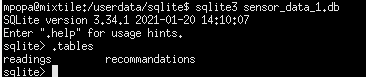
sqlite3 sensor_data.dbThis command will create a database named sensor_data. Now, we will create a table with data; for that, we will use the Debian cli and SQL console to create the table:
mpopa@mixtile:~$ sqlite3 sensor_data.db
SQLite version 3.34.1 2021-01-20 14:10:07
Enter ".help" for usage hints.
sqlite> CREATE TABLE readings (
   ...> id INTEGER PRIMARY KEY AUTOINCREMENT,
   ...> temperature REAL,
   ...> himidity REAL,
   ...> pressure REAL,
   ...> light REAL,
   ...> uv_level REAL,
   ...> timestamp DATETIME default CURRENT_TIMESTAMP
   ...> );
sqlite>
Verify if the table is created typing “.tables” in above console:
sqlite> .tables
readings
sqlite>
To view all column names from one table, type this in sqlite3 console:
PRAGMA table_info(tabel_name);
in my case:
PRAGMA table_info(readings);
The result should look like this:

PRAGMA command
To exit from sql console, type “.end” in sql console:
sqlite> .tables
sqlite> .exit
mpopa@mixtile:~$
Before configure Node-Red to use the database, I will move it to a partition with available space, in my case /home/mpopa/userdata/ and I will change the permissions:
sudo mkdir -p /home/mpopa/userdata/sqlite
sudo mv /home/mpopa/sensor_data.db /home/mpopa/userdata/sqlite/
sudo chown -R mpopa:mpopa /home/mpopa/userdata/sqlite/sensor_data.db
sudo chmod 644 /home/mpopa/userdata/sqlite/sensor_data.db
Now, we have the database created.
OBS: I observer that one column name was entered with the wrong name; for that I should enter in sqlite console and sent this command to correct the name:
mpopa@mixtile:~$ sqlite3 sensor_data.db
ALTER TABLE readings RENAME COLUMN himidity TO humidity
OBS: in case there are null records in the database, they can be deleted as follows (where “column_name” can be the name of column; in my case: temperature, humidity,…):
DELETE FROM readings WHERE column_name IS NULL;If you want to delete all records from the database, use the following command in sqlite console ( this command will delete all records but will keep the index):
DELETE FROM readings;If you want to delete the recordings and reset the record index, you need to delete the table and then to recreate with the same structure; command to delete the whole table:
DROP TABLE IF exists readings;If you want to see the data from readings table in sqlite cli, type the following command in sqlite console:
SELECT * FROM readings;These are the recorded data in database, in sqlite cli:

PRAGMA command
C. Connect database with Node-Red.
First step is to install node-red-node-sqlite package from Node-Red palette:

sqlite package for Node-Red
Next, create a new flow, add all the necessary nodes and create an UI, like in these pictures:

1/2 · Weather station Ul

2/2 · Weather station nodes
The data came from external unit through MQTT messages, as follows:
weather/temperature
weather/humidity
weather/pressure
weather/light
weather/uv_level
All these are connected to MQTT IN nodes. The chain from sensors to Mixtile are part of another project that will be documented soon.
The code for function node is this (should be write in tab “On Message”):
var temperature = msg.payload["weather/temperature"];
var humidity    = msg.payload["weather/humidity"];
var pressure    = msg.payload["weather/pressureAtm"];
var light       = msg.payload["weather/light"];
var uv_level    = msg.payload["weather/UVsensor"]
if (temperature === undefined || humidity === undefined || pressure === undefined || light === undefined || uv_level === undefined) {
return { payload: "Temp or humi or press or light or UV undefined"}
}
msg.params = [temperature, humidity, pressure, light, uv_level];
return msg;
The code for SQLIte node is this:
INSERT INTO readings (temperature, humidity, pressure, light, uv_level, timestamp) VALUES (?, ?, ?, ?, ?, DATETIME('now', 'localtime'));The data will be recorded in database with 1 minute rate.
OBS: the whole flow code for Node-Red will be available soon, in download section.
D. Installing Python
Python is used to crate scripts that will configure the ML model. To install Python, we have to follow these steps:
sudo update
sudo apt install python3
python3 --version --> to verify the installed version
Next, install pip:
sudo apt install python3-pip
pip3 --version --> to verify the installed version
Installed version on my setup:

Python3 and pip version
Next, install libraries used to work with machine learning, especially with logistic regression model:
cd /userdata
mkdir For_ML
cd /userdata/For_ML
pip install --target=. pandas scikit-learn numpy
Next, create two python files: one used to create and insert a new table, recommandations and another to populate with 5000 values that will be used to train the model. These two tables will be available in Download section after testing.
Structure of recommandations tables is this:
CREATE TABLE recommandations (
	id INTEGER PRIMARY KEY AUTOINCREMENT,
	temperature REAL,
	humidity REAL,
	pressure REAL,
	light REAL,
	uv_level REAL,
	recommandation TEXT
);
Next, itstall the following libraries used for create a logistic regression model:
pip install pandas scikit-learn numpyIn my case, I used other path to install all these libraries, on /userdata partition:
mkdir /userdata/For_ML/
cd /userdata/For_ML/
pip install --target=. pandas scikit-learn numpy
Next, install joblib library, used to save the trained model
mkdir /userdata/For_ML/
cd /userdata/For_ML/
pip install --target=. joblib
Next, create 3 python files:
In sqlite database, we will have now 2 tables:
This is the database structure, now:
database tables
Next, we have to fill the table recommandations with data that will be used for train the model; this will be done using “insert_training_data.py “. This script will fill 5000 records in the tables, based on the 15 rules created between the sensors.
1/2 · Display data from recommandation table

2/2 · Data in recommandation training table
Next, We will train the model using train_model.py. This operation take few seconds and the best result, in this case is 66.7%. Fot the moment I will take this value as best value for the training data and training rules.

Model accuracy
At the end, this script will save the model with the name “model.pkl”, in the same director (in my care, in /userdata/For_ML/):

Model location
Next, the forth script, “predict_from_readings.py” is used to predict what clothes and accessories to wear based on real data from “readings” table. This script will be applied only to the last recorded data and will be triggered at 15 minutes or at request from Node-Red.

Prediction result
Now, we have to setup Node-Red to receive the prediction value from Machine Learning model. The “predict_from_readings.py” is set to send the prediction result to Node-Red over http, on /localhost:1880/recommendation link (see this in script). In Node-red We have to add 3 nodes:

http in node in Node-Red

Response function

Node-Red http send-receive config
In this moment We have configured the communication between ML and Node-Red. Next steps are: create an automatic request for predictions, add manual request for prediction and interpretation of recommendations in Node-Red.
Create an automatic request for prediction in Node-Red. To do that add the following nodes in Node-Red:

Manual and automatic trigger for prediction
Now, the ML is finished, the Node-red configuration is finished and the Node-Red UI should look like this:

Weather station Ul with prediction
In this part will be presented some video that demonstrate how this project is working in real life.
A. Video with weather station prototype working; here, the external unit (in the left side of the video) wait until the client is connected (in the right side of the video) and then will send the environmental data with a rate at 30 seconds:
Video with weather station prototype working
B. Video with implementation of weather station with prediction for what should I wear and what accessories should I have when I go out:
Video with weather station interface
C. Video with all Zigbee devices connected to Mixtile Edge2 kit (this video also has sound to exemplify in the interdata from None-Red the fact that the buttons are pressed):
Video with Zigbee devices – with sound!!!
D. Video with Node-Red and Zigbee2mqtt UI:
Video with Node-Red and Zigbee interface
This chapter contain the next steps that can be used to improve and groth the Zigbee network and, maybe Z-Wave network, on one hand and Weather station on the other hand; and, of cource, add LoRa board to Mixtile Edge 2 kit and create a sensor and devices network usoing this protocol. Let;s take one by one.
In this part will be presented some video that demonstrate how this project is working in real life.

Almost no space on /dev/root partition
In this case, I have 2 options:
1. I ask Mixtile how to solve the space issue;
2. Move some folders from /dev/root partition to the larger one, /userdata
For option 1, Mixtile offered me a new Debian image with the new partitions resized; but flashing of this new image will erase all the settings that I have made until now;
For option 2 (more challenging…), first I located the larger folders from the system with command:
sudo du -h --max-depth=1The result is this:

List with large folders from the system
Then, I moved the following folders to /userdata and I created for each folder an symbolic link:
a./var/cache/apt moved to /userdata (send one commnad at the time):
sudo mv /var/cache/apt userdata/apt_cache     --> move the folder
sudo ln -s /userdata/apt_cache /var/cache/apt --> create the symbolic link
sudo chown -R root:root /userdata/apt_cache   --> set permisions
sudo chmod -R 755 /userdata/apt_cache         --> set permitions
sudo systemctl restart apt=daily.service      --> restart the service for apt

optional, after that, send this to rebuild all necessary files in new location:
sudo apt-get update
b./opt moved to /userdata:
sudo mv opt /userdata/opt  --> move the folder
sudo mount --bind /userdata/opt /opt --> mount the folder /userdata/opt instead /opt
/userdata/opt /opt none bind 0 0 --> add this line in file /etc/fstab
To modify the file fstab from /etc/fstab, send these commands:
sudo mount -o remount,rw /  --> make the files writable
sudo nano /etc/fstab        --> open file fstab to edit
The result:

File fstab modified
c. /Downloads moved to /userdata:
mv ~/Downloads /userdata/Downloads    --> move the folder
ln -s /userdata/downloads ~/Downloads --> create the symbolic link
d. /Arduino moved to /userdata (this is specific for Arduino IDE):
mv /home/mpopa/Arduino /userdata/Arduino    --> move the folder
ln -s /userdata/Arduino /home/mpopa/Arduino --> create the symbolic link
e. /.arduino15 moved to /userdata (this is specific for Arduino IDE):
mv /home/mpopa/.arduino15 /userdata/.arduino15    --> move the folder
ln -s /userdata/.arduino15 /home/mpopa/.arduino15 --> create the symbolic link
Obs here: the folder.arduino15 is hidden; for that I have to go in /hone/mpopa and, from UI, selected View and Show Hidden Files.
Now, the folder /userdata and the space on /dev/root should look like this:

1/2 · New space created on root

2/2 · userdata folder with the new folders

I am working as a test engineer for navigation systems in auto industry. I am passionate about science, loT, ML, MCU programming, and SF movies.